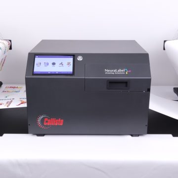
Opening the Printer for Inspection of LEDs and Boards Required for Major Component Replacement
This video shows the basic steps for opening and closing the Callisto printer. It should be viewed before doing any work inside the printer.
Identify LED Lights and components
In this video we identify LED lights and their associated components inside the Callisto printer. We first view the lights at the exit side of the printer. Then open up the printer for further inspection. We view the lights and components inside the printer. And then reclose the printer.
From the printer exit, view the network, main PCA and Main PC lights. Also the Controller, or OEM2, Heartbeat and Power LEDs.
Open the Printer
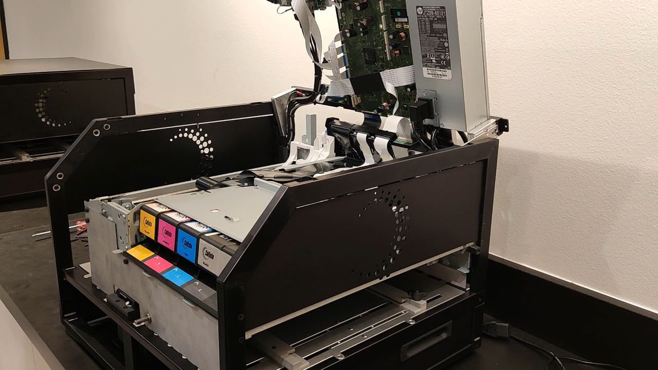
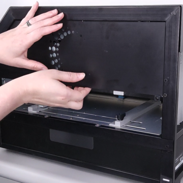
Now let’s open up the printer to look inside it. Turn the printer off with the power button. Then turn off the back switch and unplug the power and network cables. Locate 6 screws that attach the cover and unscrew with a Phillips screwdriver. Carefully remove the printer cover, making sure the cover does not catch on the round power button. Lift up the printer electronics tray and secure with the kick stand. Be extremely careful to properly secure the electronics tray with the kickstand.
Inspect Printer Interior
Now let’s inspect the printer interior. Locate the Main PCA and Controller boards. Locate connectors for printer components. With the printer open, reattach the power and network cables. Turn the printer on with the back switch. It will take a couple of minutes for the printer to boot. Identify components and lights inside the printer.
Close the Printer
Now let’s close the printer. First, we’ll turn it off and remove the power and network cables. Very carefully unlatch the kickstand and slowly lower the electronics tray, aligning the slots. Carefully replace the cover aligning the power button slot. Reattach the cover with the Phillips screws. Be sure not to over-tighten the screws.
Contact our support group if you have questions.

