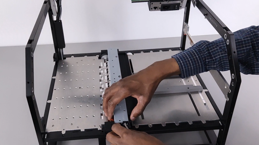
This video provides instructions for replacing the Upper Media Guide within the Callisto printer. The printer must be powered off and open, and the BnB removed prior to replacement. Please watch those instructional videos before attempting to remove the upper media guide.
A Phillips screwdriver is required for this procedure.
Removing the Upper Media Guide
There are 4 screws and two connections to disconnect. First, disconnect the connector at the front of the printer. There is a black latch that sits on the back of this connector. Using your finger, flip the latch up towards the blue backing. Keep them flat and pull away from the connector to disconnect. Feed the wires out of their slots to move them out of the way.
Next, there are four screws, two on each mount. Using the screwdriver, unscrew and completely remove each screw. Then the mount should lift straight up and out of the printer. Notice that each mount is different. The one at the front of the printer has a screw in it, and the one at the back of the printer does not have a screw in it.
Now you can gently pull up and tilt the upper media guide. There is one more connector at the back of the printer. Disconnect it by holding the upper media guide and pulling the connector down and away from the guide. Once disconnected, the upper media guide can be removed from the printer. When setting it down, ensure it is not sitting on the contacts or the idler.
Installing the Upper Media Guide
First, reconnect the green connector at the back of the printer. There is a ramp on the front of this connector. Make sure the ramp is facing the front of the printer, then push the connector into place. This is a friction lock.
Next, reinstall the two mounts. The front mount has a screw in it, and the back mount does not have a screw in it. Starting with the front mount, use the placement screw to align the mount with the upper media guide by setting it into the positioning hole. Screw both screws in until they are just touching the mount.
Take the connection at the front of the printer, and feed the connector with the flag on it through the left slot in the mount. Next, take the second connector and feed it through the second slot in the mount. To connect the two, flip the black latch on the back and insert the flag into the front of the connector, then close the clip to complete the connection.
Next, set and screw down the back mount. Screwing both screws in until they are just touching the mount. Once the guide is in place and connected, tighten all four screws. Do not over-tighten.
If you have any questions, Contact Support or visit the Support Library for more information.


